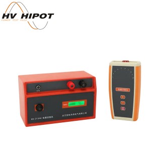
GD-2134E Cable Identifier (Model GD-2134E)


• Multiple detection modes: classic positioning mode, wire cruise mode, signal curve mode.
•Classic positioning mode: compass, direction and signal amplitude display, intuitive display of the left and right directions of the pipeline.
•Wire cruise mode: 360°all-round pipeline path indication, continuous display of depth, current and relative position of pipeline. The interface is simple and intuitive, and can be operated without experience.
•Signal curve mode: can display historical signal strength curves, and find the cable location by observing the changes in signal strength curves at different locations.
•Current direction determination (partial frequency), by calibrating the current direction, eliminating interference from adjacent lines and preventing tracking errors.
•Built-in sweep frequency test function, users can select the appropriate signal frequency for pipeline measurement through the sweep frequency results to avoid co-frequency interference.
•Fully digital high-precision sampling and processing: stable and reliable, ultra-high sensitivity, extremely narrow receiving passband, strong anti-interference ability, and can fully suppress the power frequency and harmonic interference of adjacent running cables and pipelines.
•Ground fault search (optional function): The transmitter transmits the positioning signal to the faulty cable. The A-frame (optional accessory) can be used to locate the ground fault location point of the pipeline, and the arrow indicates the positioning direction.
•Multiple detection frequencies: 12 active detection frequencies and 4 passive detection frequencies.
•Multiple signal output modes of the transmitter: direct connection output, clamp coupling output, radiation induction.
•Transmitter digital amplification power output, fully automatic impedance matching, and fully automatic protection.
•The instrument has a built-in high-brightness light under it for easy night operation.
Receiver
|
Function |
Pipeline detection (cable position tracking, direction display, depth measurement, current measurement), cable identification, pipeline grounding fault detection. |
|
Power Supply |
7.4V DC 3400mAh rechargeable lithium battery |
|
Input method |
Built-in receiving coil, flexible caliper, earphone |
|
Receiving Frequency |
Active detection frequency: 577Hz, 640Hz, 1280Hz, 2.56kHz, 3.20kHz, 4.09kHz, 8.19kHz, 10kHz, 33kHz, 66kHz, 82kHz, 201kHz
Power frequency passive detection frequency: 50Hz, 250Hz RF passive detection frequency band: center frequency is divided into 33kHz, 82kHz |
|
Pipeline Detection Mode |
Wide peak method, narrow peak method, sound valley method |
|
Pipeline Detection Display |
Classic positioning mode, wire cruise mode, signal curve mode |
|
Pipeline Detection Range |
Direct connection method: generally can reach cable length of 0~20 kilometers, mainly determined by ground resistance, cable resistance and cable buried depthgenerally can reach cable length of 0~10 kilometers, mainly determined by ground resistance, cable resistance and cable buried depth
Induction method: suitable for cables buried less than 2m. |
|
Depth and Current |
Automatically read cable depth and current value |
|
Pipeline Measurement Depth |
0~20m |
|
Depth Accuracy |
Planar position precision positioning accuracy: center axis position of target cable or pipeline:
±5% (buried depth 0~3m), ±10% (buried depth 3m~20m) |
|
True or False Tips |
Eliminate interference from adjacent cables. When measuring adjacent cables, the measurement of adjacent cables can be distinguished based on the different signal strengths and measured current phases of the adjacent cables. In the process of tracing the cables, observe the phase dial and pointer direction to distinguish the measured cable from the adjacent cables. |
|
Sound Indicator |
FM tone that varies with signal strength |
|
Anti-interference Ability |
Extremely narrow receiving frequency band, unique digital processing method, can fully suppress the power frequency and harmonic interference of adjacent running cables and pipelines |
|
Interference Distance |
When using the coupling method and the induction method, the transmitter will generate interference within a short distance. The interference distance is related to the transmission power and frequency. The greater the power and the higher the frequency, the stronger the interference.
The minimum distance at which the receiver is not interfered by the transmitter often needs to be determined by experiment: Pipeline detection: 5m away for the coupling method and 20m away for the induction method can be confirmed as no interference Cable identification: 2~5m away for the coupling method can be confirmed as no interference |
|
Cable Identification |
Identification method: flexible clamp intelligent identification, stethoscope identification;
Number of calibrable cables: 1 to 10; Calibration value: The current percentage of the receiving signal and the transmitting signal is between 75% and 135% of the calibration value, which is one of the conditions for successful identification; Directionality: The transmitting clamp, the receiving clamp and the loading signal must be in the same direction, which is one of the conditions for successful identification. |
|
Cable Identification Detection Range |
Direct connection method: can identify signals with a loop resistance of 0Ω~8kΩ (generally can reach a cable length of 0~20 kilometers, mainly determined by the ground resistance and cable resistance)
Coupling method: can identify signals with a loop resistance of 0Ω~1kΩ; (generally can reach a cable length of 0~6 kilometers, mainly determined by the ground resistance and cable resistance) |
|
LED Night Lighting |
The receiver has an LED flashlight function |
|
LCD |
3.5-inch color LCD |
|
Dimensions |
Approximately 290mm (length)*128mm (width)*700mm (height) |
|
Weight |
Approximately 1.90kg |
|
Charger |
DC 8.4V 1A |
|
Lighting Power |
1W max |
|
Connection Interface |
1*Mini-B USB port (for firmware upgrade)
1*DC charging port 1*Flexible caliper connection socket |
|
Flexible Current Clamp |
Length about 620mm, wire diameter about 8mm |
|
Inner Diameter of Coil |
200mm (can be customized with larger diameter as needed) |
|
Stethoscope size |
111mm*60mm*27mm (optional) |
|
Lead length |
About 3m |
|
Working Temperature & Humidity |
-10℃~40℃;80%Rh and below |
|
Storage Temperature & Humidity |
-10℃~50℃;≤95%RH, no condensation |
|
Withstand Voltage |
AC3700V/rms (between the upper and lower ends of the housing) |
|
Safety Compliance |
IEC61010-1 CAT Ⅲ 600V,IEC61010-031,IEC61326,pollution level 2 |
Transmitter
|
Function |
Multiple frequency signal transmission methods |
|
Power Supply |
11.1V DC 12800mAh rechargeable lithium battery |
|
Output Method |
Direct connection mode, clamp coupling mode, induction mode |
|
Output Frequency |
577Hz,640Hz,1280Hz,2.56kHz,3.20kHz,4.09kHz,8.19kHz,10kHz,33kHz,66kHz,82kHz,201kHz |
|
Output Power |
10W max, 10 levels adjustable |
|
Impedance |
Fully automatic real-time impedance matching and protection function |
|
Direct Output Voltage |
150Vpp max |
|
Circuit Protection |
With overload and short circuit protection |
|
LCD |
5.6-inch LCD color screen |
|
Dimension |
Approximately 320mm (length)*275mm (width)*145mm (height) |
|
Weight |
Transmitter weight about 3.85kg; Transmitter clamp weight about 1.18kg |
|
Charger |
DC 12.6V 2A |
|
Transmitter Clamp Size |
297mm×194mm×39mm |
|
Transmitter Clamp Inner Diameter |
φ150mm |
|
Transmitter Clamp Wire Length |
3m |
|
Test Wire |
Red test line 3m, black test line 3m |
|
Connection Interface |
1*Type-B USB port (for firmware upgrade)
1*DC charging port 1*signal transmitter clamp connection socket 2*direct test line interface |
|
Pressure-resistant |
The transmitter adopts an integrated special tool box design, and the box can withstand a pressure of about 200kg |
|
Withstand Voltage |
AC 3700V/rms (Between the top and bottom of the instrument case) |
|
Electromagnetic Characteristics |
IEC61326(EMC) |
|
Safety Compliance |
IEC61010-1(CAT Ⅲ 300V、CAT IV 150V、pollution level 2) |