First of all, we can understand that the dielectric loss is that the dielectric is under the action of an electric field. Because of the internal heating, it will convert electrical energy into heat energy and consume it. This part of the consumed energy is called dielectric loss.
Dielectric loss not only consumes electric energy, but also heats up equipment components and affects its normal operation. If the dielectric loss is large, it will cause overheating of the medium, resulting in damage to the insulation, so the smaller the dielectric loss, the better. This is also one of the important quality standards of the dielectric in the AC electric field.
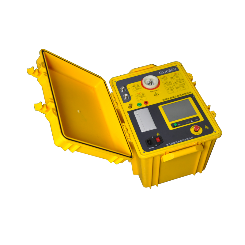
GD6800 Capacitance and Dissipation Factor Tester
Let’s talk about how to use the dielectric loss tester to measure the dielectric loss of the transformer. After we start the instrument for measurement, the high voltage setting value is sent to the variable frequency power supply, and the variable frequency power supply uses the PID algorithm to slowly adjust the output to the value to be set, and then the measured circuit will send the measured high voltage to the variable frequency power supply, and then Fine-tuning the low voltage to achieve accurate high voltage output. In this way, according to the setting of positive/reverse wiring, the instrument will intelligently and automatically select the input and switch the range according to the test current of the measurement circuit.
When measuring the dielectric loss of the high-voltage winding to the low-voltage winding and the shell of the power transformer, we use the reverse connection method to measure. After the instrument and the power transformer are connected correctly, we use different frequency, 10kV voltage measurement, and the reverse connection method. This method is used when the low-voltage measuring terminal or secondary terminal of the test object cannot be insulated from the ground and is directly grounded. The instrument adopts Fourier transform to filter the interference and separate several waves of the signal, so as to perform vector calculation on the standard current and the test current, calculate the capacitance by the amplitude, and calculate the tgδ by the angle difference. After multiple measurements, an intermediate result is selected by sorting. After the measurement is over, the measurement circuit will automatically issue a step-down command. At this time, the variable frequency power supply will slowly step down to 0.
Post time: Mar-22-2023