The insulation resistance tester is mainly used to measure the insulation resistance of large transformers, transformers, generators, high-voltage motors, power capacitors, power cables, arresters and other equipment.
GD3127/3128 Insulation Resistance Tester
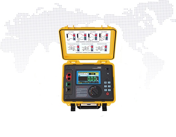
Operation and test steps of the insulation resistance tester:
(1) The shaker should be selected according to the voltage level of the equipment. For transformers of 10KV-35KV, a 2500 volt shaker should be used.
(2) Before measuring the insulation resistance, the power supply of the equipment under test should be cut off, and the Carry out short-circuit discharge, the purpose of discharge is to protect the safety of people and equipment, and to make the measurement results accurate;
(3) The connection of the shaker should be two separate single wires (two colors) with good insulation, two Do not twist the connecting wires together, and do not make the connecting wires contact the ground, so as to avoid errors caused by poor insulation of the connecting wires;
(4) Before measuring, perform an open circuit and short circuit test on the shaker to check whether the shaker is in good condition and the transformer is insulated. If the resistance tester opens the two connecting lines and shakes the handle, the pointer should point at ∞ (infinity). At this time, if the two connecting lines are momentarily short-circuited, the pointer should point at 0, which means that the shaker is in good condition. , otherwise there is an error in the shaking table;
(5) The wiring method of shaking the insulation resistance of the primary winding to the secondary winding and the ground (shell): Short-circuit the three-phase terminals lU, lV and 1W of the primary winding with bare copper wires , in order to connect to the “L” end of the megohmmeter; short-circuit the terminals N, 2U, 2V, 2W and the ground (earth crust) of the secondary winding with bare copper wires, and then connect them to the “E” end of the megohmmeter; if necessary , in order to reduce the influence of surface leakage on the measured value, the bare copper wire can be wound on the porcelain skirt of the primary side porcelain sleeve for a few turns, and then connected to the “G” end of the megohmmeter with an insulated wire;
(6) Shake the measurement of the secondary winding pair The wiring method of the insulation resistance of the primary winding and the ground (shell): short-circuit the 2U, 2V, 2W, and N terminals of the secondary winding with bare copper wires. In order to connect to the “L” end of the megohmmeter; after short-circuiting the three-phase leads 1U, 1V, 1W and ground (shell) of the primary winding with bare copper wires, connect them to the “E” end of the megger; To reduce the influence of surface leakage on the measured value, a bare copper wire can be wound around the porcelain skirt of the secondary side porcelain sleeve for a few turns, and then connected to the “G” end of the megohmmeter with an insulated wire.
(7) When measuring, press the shell of the shaker with one hand (to prevent the shaker from vibrating). When the pointer indicates 0, stop shaking immediately to avoid burning the watch;
(8) When measuring, place the shaking table in a horizontal position, turn the shaking handle of the generator at a speed of about 120 revolutions per minute, and read at 15s Take a number (R15), read another number (R60) at 60s, and record the shaking data.
Post time: Jan-12-2022