The measurement methods of the ground resistance tester usually have the following types: two-wire method, three-wire method, four-wire method, single clamp method and double clamp method, each has its own characteristics. In actual measurement, try to choose the correct method to make the measurement The results are spot on.
1. Two-line method
Condition: There must be a ground known to be well grounded. Such as PEN and so on. The measured result is the sum of the resistance of the measured ground and the known ground. If the known ground is much smaller than the resistance of the measured ground, the measurement result can be used as the result of the measured ground.
Applicable to: buildings and concrete floors, etc. Seal areas where ground piles cannot be driven.
Wiring: e+es receives the ground under test. h+s receive known ground.
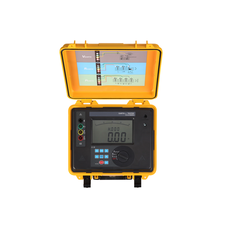
GDCR3100C Earth Resistance Meter
2. Three-line method
Condition: There must be two ground rods: one auxiliary ground and one detection electrode, and the distance between each ground electrode is not less than 20 meters.
The principle is to add current between the auxiliary ground and the ground under test. Measure the voltage drop measurement between the ground under test and the probe electrodes. This includes measuring the resistance of the cable itself.
Applicable to: ground grounding, construction site grounding and lightning ball lightning rod, QPZ grounding.
Wiring: s connected to the detection electrode. h connected to the auxiliary ground. e and es are connected and then connected to the measured ground.
3. Four-wire method
It is basically the same three-wire method. When the three-wire method is used instead of the three-wire method, the influence of the measurement cable resistance on the low ground resistance measurement results is eliminated. When measuring, e and es must be directly connected to the measured ground respectively, which is very accurate in all ground resistance measurement methods.
4. Single clamp measurement
Measure the grounding resistance of each position in the multi-point grounding, and do not disconnect the grounding connection to prevent danger.
Applicable to: multi-point grounding, cannot be disconnected. Measure the resistance at each connection point.
Wiring: Use current clamps to monitor. Current at the location being tested.
5. Double clamp method
Conditions: multi-point grounding, no auxiliary grounding pile. Measure the ground.
Wiring: Use the current clamp specified by the manufacturer of the grounding resistance tester to connect to the corresponding socket. Clamp the two clamps on the grounding conductor, and the distance between the two clamps should be greater than 0.25 meters.
Post time: Feb-15-2023